How To Build A Reverse Polarity Voltage Inverter For Positive Ground Effects Pedals
Most of the pedals you purchase or build will utilise the standard 9 volt negative ground power supply using a 2.1mm barrel jack. However, some pedals, mainly those which use vintage germanium transistors, will require a slightly different power supply.
These vintage germanium transistor pedals may require a 9 volt positive ground power supply instead of a negative ground power supply. Whilst this may not seem like a huge difference, the polarity of your power can be the difference between your pedal working perfectly and it not working at all. Or worse, a power supply the wrong polarity can fry your pedal to the point where it will not work again.
There are a few ways to handle guitar effects pedals that require a positive ground power supply. I actually cover a few of them in my blog post here:
How To Handle Positive Ground Guitar Effects Pedals
However, if you’re building your own effects pedals, you may wish to create an internal solution to help ensure your customers can utilise their standard power supply along with their other pedals. The less they have to worry about with your pedals, the happier they will be with them.
So, how do we create a solution like this?
Well, we can use a simple polarity voltage inverter circuit to transform the negative ground power into the positive ground power that the rest of the circuit requires.
In this guide, I’ll show you how to create the most basic version of this circuit to get you up and running.
Items Needed
Here’s a list of the items we’ll need to build a reverse polarity voltage inverter:
- 1 10uF Electrolytic Capacitor
- 1 47uF Electrolytic Capacitor
- 1 ICL7660S or MAX1044 Integrated Circuit
- 4 Small Lengths Of Wire
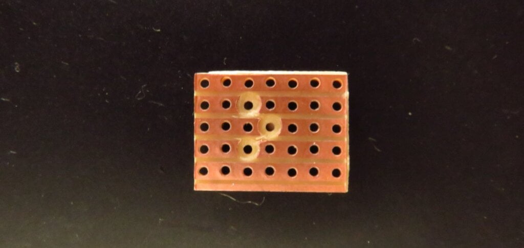
- 1 7×5 Piece Of Strip Board
- 1 8 Pin IC Socket
Wiring Diagram
Building the reverse polarity voltage inverter for DIY guitar effects pedals is incredibly simple and it really only requires 3 main components. Here is a wiring diagram of how the components fit together to create this pedal and what the pedal will roughly look like once you’ve finished it.

As you can see from the 9 volt reverse polarity schematic above, this is an incredibly simple build which you should be able to put together within an hour.
Build
To get started with this build, gather all of your components and lay them out in front of you. This will make them easier to grab whilst you’re soldering everything together.
Turn your soldering iron on and leave it for a few minutes to warm up. If you’re just starting out and not sure which soldering iron to get, check out my essential equipment for DIY pedal making guide. Whilst the soldering iron gets up to the correct temperature, we can strip the shielding off the end of your lengths of wire. Using your wire strippers, remove the plastic shielding to expose the metal wire beneath. This is what you will use to connect this circuit to our existing effects pedal.
Once your soldering iron is up to temperature, we can prepare all of our components and tin them with a bit of solder to make connecting them to our board, much easier.
As we’re working with stripboard, I would suggest making the 3 necessary cuts first. These cuts can be found at B3, C4 & D3 of my above layout. A great way to test that these cuts have been successful is to use your multimeter in continuity mode. If you place each of the probes at opposite ends of each strip, the rows with the cuts shouldn’t show any signs of continuity. If they do, go back and check your cuts.
Next, I usually move on to the connections. In this circuit, we have only one connection between C3 and E3. If you have any old leads from resistors or capacitors that you’ve trimmed in a past project, these make for fantastic connectors. They’re super easy to work with and they avoid waste.
This circuit uses an integrated circuit (IC). As with most semiconductors, I prefer to use sockets wherever possible as this makes it much easier to swap them out at a later date if necessary. With this in place, you can seat the IC. Pay attention to the orientation of it with the dimple pointing to the top of the board. Please check the layout for a clearer view of this.
After that, we can move on to the two electrolytic capacitors. Please take note of the orientation of these components as they are polarised. If placed in this circuit the wrong way round, it may create problems for the circuit.

Finally, we can solder on the jumper wires to connect this board to both the power supply jack and the voltage in & ground of the actual pedal.
Before you install everything into your enclosure, I’d strongly recommend that you test it out. This is a good practice to get into as it will save you lots of error checking time in the future with more complex builds.
If it works, excellent! Let’s go ahead and put everything together. If it doesn’t work for some reason, go back and check your solder joints to make sure you have solid connections. You can find my guide here on troubleshooting DIY guitar effects pedals.
There we go, a super simple circuit to help make your negative ground power supply work with positive ground effects pedals.
If you hit any issues while building this, please let me know as I’m here to help and answer any questions you may have.
Happy building!
