How To Build An Op-Amp Buffer Pedal
If you hang around in any gear forum long enough, you’ll have heard about the most expensive and most mythical pedal of them all. The Klon Centaur.
Overview
Inside the Klon Centaur pedal is this operational amplifier (Op-Amp) buffer. We can either use a TL071 chip or a TL072 chip but either way, you’ll end up with a fantastic buffer in your signal chain. The benefits of this type of buffer are that you won’t hear any compression from it and that it will really bring out the high-end frequencies of your signal.
Parts List
This is a fairly easy build with only 10 components:
Components
R1 – 100K Resistor
R2 – 100K Resistor
R3 – 1M Resistor
R4 – 100K Resistor
R5 – 560R Resistor
C1 – 47uF Electrolytic Capacitor
C2 – 100nF Film Capacitor
C3 – 1uF Electrolytic Capacitor
IC – TL072
D1 – 1N4001
Hardware
2 ¼ Inch Mono Input Jacks
DC Input
8 Pin IC Socket
1590A Hammond Enclosure
Preparation
There are a couple of different options when building this buffer. You can either build it using the kit/PCB from FuzzDog or you can build it using stripboard.
Here is a link to the kit from FuzzDog:
https://shop.pedalparts.co.uk/Klon_Buffer/p847124_6346591.aspx
If you’re happy to source your own components and looking to save a bit of money, why not check out their standalone PCB:
https://shop.pedalparts.co.uk/Klon_Buffer/p847124_12489370.aspx
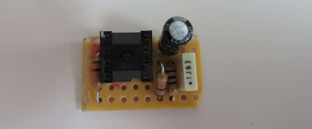
The other option is to build it on stripboard and this is how I built my buffer using the below schematic:
http://tagboardeffects.blogspot.com/2011/04/klon-buffer.html
This is a little different to the version from the FuzzDog kit as it doesn’t include a rectifier diode to protect the circuit from an incorrect voltage supply, but the principles are the same.
Before starting out with any build, I like to take all of the components necessary for a pedal and lay them out on a labelled sheet of paper. This will make it easier to pick up each piece as and when they’re needed for the build. It will also let me see if there are any missing components before I start a build.
With everything laid out in front of you on your labelled sheet of paper, turn your soldering iron on to get it heated up to the necessary operating temperature. Whilst you’re waiting for this to heat up, grab a dry cloth or a tissue and wipe down the PCB/stripboard and the leads for all of your components to remove any oil or grease. Giving them a quick clean will help ensure you get as good a connection as possible when soldering your components into place.
Build
Once your soldering iron is up to the correct temperature and your PCB/stripboard has been wiped down we’re ready to start building.
As always with any build, we want to start with our lowest profile components as this will make it much easier to build up our board. With this in mind, we’ll start off with our resistors. Take your needlenose pliers and bend the resistor connectors 90-degrees a few millimetres from the edges of the resistor. This will make it easier to add them to your board and it will also make everything look much neater at the end. The cleaner your board is at the end of the build, the easier it will be to troubleshoot any issues should they arise.

With all of the resistors in place, we can move onto the integrated circuit (IC) socket. Ensure you take note of how the IC should be orientated on your board as this could create issues when you come to test the buffer. If you’re using the PCB from FuzzDog, make sure the dot (pin 1) on the IC is at the same end as the imprint on the PCB visuals. The use of a socket will mean we hot swap IC’s if the one we initially use doesn’t work for any reason.
With the IC socket in place, we can move onto the film capacitor. This should be the next tallest component of our build. For this circuit, we have one film capacitor which can be soldered onto the board in any orientation. However, we also have two electrolytic capacitors which are polarised components. Please take special care to ensure that they are correctly orientated. The long leg of your capacitor, the anode, goes to the square pad of the PCB (if you’re using the FuzzDog PCB).
Finally, if you’re using the FuzzDog PCB, you can add the diode. Just like the electrolytic capacitor, this is a polarised component. The striped end of the diode, the cathode, goes onto the square pad of the board. Any other orientation will mean that the buffer won’t work.
The circuit is now complete and ready to test.
Test The Buffer
Before adding this completed circuit into your buffers enclosure, I would highly recommend that you test it out to make sure that it actually works. This will make it much easier to reflow any dry solder joints or swap out any dead components if required. Once this circuit is fitted into the enclosure, it will be a little more difficult to troubleshoot.
Wire this circuit up directly to the input jacks and a DC input jack. The wiring here doesn’t need to be neat as we’ll be redoing all of this inside of the enclosure once we know everything works.
If our new JFET buffer works, we can move onto the next phase. However, if you spot any issues, why not work through my DIY guitar effects pedal troubleshooting guide.
Drill The Enclosure
As this is a standard buffer with no extra features, we only have three holes to drill. One for the input jack, one for the output jack and one for the power jack.
Below is a guide for how big each of these holes needs to be:
2 Input Jacks – 10mm
1 DC input Jack – 12mm
Final Assembly
Now that we have tested the Klon style buffer to make sure it works correctly and drilled the enclosure, we can start piecing everything together into a complete pedal.
I’d suggest installing all of the hardware first and tightening all of the nuts to ensure there’s no unnecessary movement.
With all of the hardware in place, you can start adding all of the connection wires between the input jacks, power jack and circuit board/PCB. As everything is now fixed into place, you should be able to cable manage your pedal much more efficiently. You want everything to look as neat as possible as unnecessarily long connection wires may create interference and will make any future troubleshooting a little more difficult.
Final Thoughts
As with all buffers, this is a super simple pedal to create and whilst it may not be the most exciting item on your pedalboard, it can really improve your guitar tone if you have a larger guitar rig.
If you’re new to building pedals and not comfortable working within the confined space of a 1590A enclosure, why not start out with the 1590B or 125B enclosure? This will give you a little more room to work with whilst you build up your confidence. You can always rehouse it at a later date if you want to save a bit of space.
If you have any questions about this build, please let me know.
