DIY Tap Tempo Footswitch
A Tap tempo footswitch is a very versatile pedal and can be used in conjunction with other pedals to unlock their full potential.
Sometimes referred to as an external tap tempo switch, it’s a very simple momentary footswitch which will help you control the tempo of your pedals’ effect.
You can use a tap tempo footswitch with a delay to tap in the exact tempo of the song rather than fiddling with the inbuilt controls to estimate it.
Tap tempo pedals aren’t just limited to delay pedals and can be used with echo’s, tremolo’s and reverb pedals to mention a few.
As these are passive pedals, we don’t need to worry about powering them with a 9volt battery or power supply.
Items Needed
Here’s a list of the items we’ll need to build a DIY tap tempo footswitch:
- 1 ¼ Inch Mono Jack Input
- 1 Momentary Push Button Foot Switch SPST
- 1 Hammond 1590LB Enclosure
- 2 Small Lengths of Wire
Wiring Diagram
Building your own DIY tap tempo pedal is incredibly easy and would make for a fantastic first project to supplement your existing pedalboard. Here is a wiring diagram of how the components fit together to create this pedal and what the pedal will roughly look like once you’ve finished it.

As you can see from the tap tempo pedal schematic above, this is an incredibly simple build which you should be able to put together within an hour.
Build
To get started with this build, gather all of your components and lay them out in front of you. This will make them easier to grab whilst you’re soldering everything together.

Turn on your soldering iron and leave this to warm up. If you’re just starting out and not sure which soldering iron to get, check out my essential equipment for DIY pedal making guide. Whilst the soldering iron gets up to temperature, we can strip the shielding off the end of your lengths of wire. Using your wire strippers, removing the plastic shielding will expose the metal wire which you will use to connect between the parts. You should only need about 5mm of exposed wire to connect these wires to our components.
Once your soldering iron is up to temperature, we can prepare all of our components and tin them with a bit of solder to make soldering your wires to them much easier.

As this build only requires two wires, we can start with these. Solder one wire to the sleeve of your mono input jack and the other to the tip.
With the wires attached to the input jack, it’s time to connect them to our momentary footswitch. As you can see from our wiring diagram, the wire coming from the sleeve of the input jack goes to one terminal and the wire from the tip goes to the other terminal. It doesn’t matter too much which way round you solder these wires as long as you have one wire going to each of the terminals.
Before you install this to your enclosure, I’d strongly recommend that you test it out. This is a good practice to get into as it will save you lots of error checking time in the future with more complex builds.

If it works, excellent! Let’s go ahead and put it everything together. If it doesn’t work for some reason, go back and check your solder joints to make sure you have solid connections. We need to make sure that the wires don’t move when you give them wiggle.
This pedal only requires two holes for your enclosure. One for the jack and one for the footswitch. The mono jack input will require a 10mm hole and the footswitch will require a 12mm hole. A good step drill bit will do the job but if you’re using a standard drill bit, you will probably need to run a file or some sandpaper over the holes to smooth out any jagged edges.
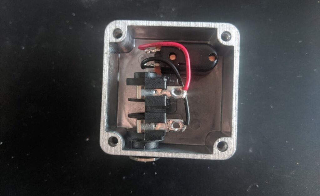
Once you have drilled both of the necessary holes, you can assemble everything in the 1590LB enclosure. Make sure all of the nuts are tightened as much as possible. You don’t want any movement when your stomping on this pedal, inputting the tempo of your song. If the wires are too long, simply desolder the connections from the jack input, trim them down to the correct length and then reattach them. I always suggest detaching them from the jack instead of the momentary switch as the solder lugs on a jack input are generally much larger and easier to work with.
When you’re happy with it, give it another test and everything should work perfectly. The only thing left now is to add your personal touch and paint it to stand out on your pedalboard so you can see it on a dark stage when you need to tap in your tempos.
I also like to date my pedals when I finish them so I can keep track of what I’ve made and when, but this is a personal preference.

There we go, a super simple DIY tap tempo footswitch which will help you make full use of your time-based guitar effects pedals.
If you hit any issues while building this, please let me know as I’m here to help and answer any questions you may have.
Happy building!
