DIY ZVex Super Hard On Pedal Build
The ZVEX Super Hard On booster pedal is a classic one knob boost pedal that can really push your amp with a lot of power.
Overview
Build Difficulty – 1/5
Build Time – 1 – 2 Hours
Pedal Style – Boost
Total Cost – ~£30
Parts List
This is a fairly easy build with only 10 components for the PCB. I purchased this PCB from FuzzDog. You can find it here:
They do also offer a full kit if you’d prefer to go down this route:
Fuzz Dog Boner Boost Pedal Kit
Components
R1 – 10M Resistor
R2 – 10M Resistor
R3 – 5K1 Resistor
R4 – 100K Resistor
R5 – 2K2 Resistor
C1 – 100nF Box Capacitor
C2 – 10uF Electrolytic Capacitor
D1 – 9.1v zener
Q1 – BS170
Gain – 5KC (Reverse Logarithmic) Potentiometer
Hardware
2 ¼ Inch Mono Input Jacks
DC Input
5mm LED
LED Bezel
3PDT Footswitch
3PDT Footswitch Daughterboard (Optional)
1590B/1590A Hammond Enclosure
Preparation
When starting with any pedal build, I always get my components together and lay them on a labelled sheet of paper. This not only helps me pick up each component as and when it’s needed but also highlights any missing components before you start.
Now that you have everything laid out in front of you, it’s time to turn on your soldering iron and get it up to temperature. Whilst you’re waiting for this to heat up, grab a cloth or a tissue and wipe down the PCB and the connectors for all of your components. Giving them a quick clean will help ensure all of your connections are good.

Build
Once you have your components cleaned and laid out in front of you and your soldering iron is up to the correct temperature, we can get started.
I always like to start a build with the resistors as they’re low profile and do not restrict your access to the rest of the board. Ideally, we would use metal film resistors for this build as they have the lowest noise level. However, carbon film resistors will also work just fine.
Add your resistors one at a time, solder it into place, make sure it’s as flush to the board as possible and then snip off the excess wire that’s poking through the other end of the board.
Rinse and repeat this step for all 5 of the resistors needed for the ZVex Super Hard On boost pedal and once they’re all in place, take the time to inspect your joints. If there are any gaps in your joints, take this time to add a bit more solder as the connection may not be as good as we need in order to get this pedal working.
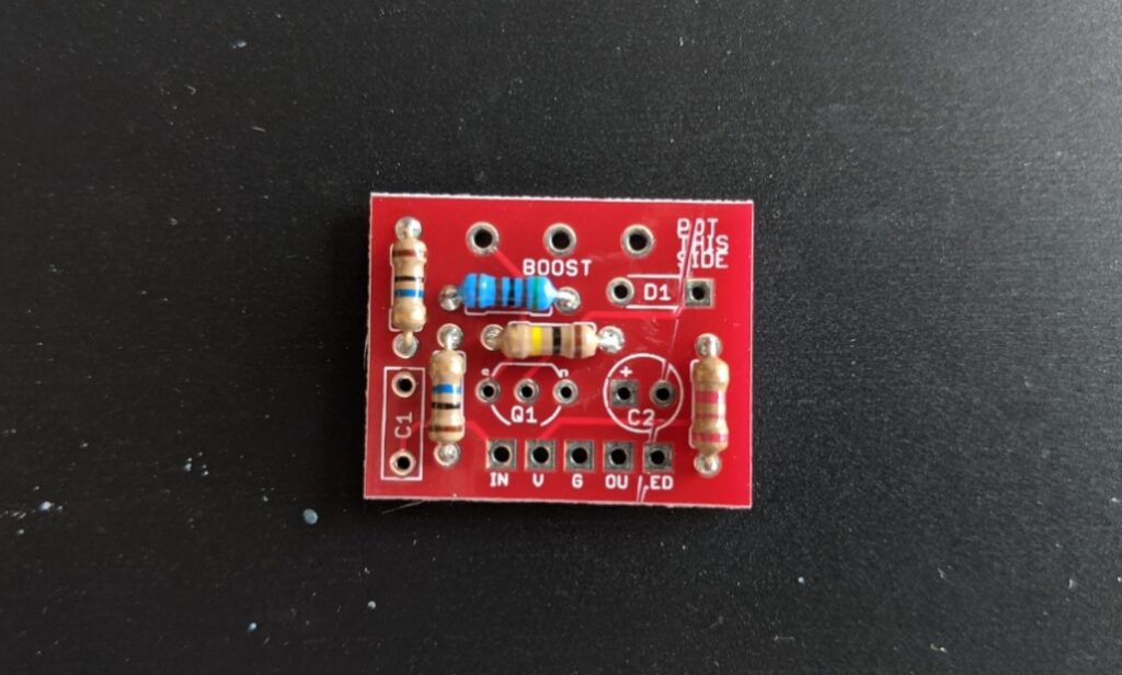
Once you’re happy with all of your resistors and that they all have made a good solid connection, we can move onto the capacitors.
This pedal only requires two capacitors. One box capacitor and one electrolytic capacitor. Both of these capacitors go on the same side of the board as your resistors as we’re not really struggling for space on this build. The box film capacitor, like your resistors, isn’t polarised so there’s no need to arrange them in a specific way. However, your electrolytic capacitor is polarised and has to be orientated in the correct way round for this to work properly. On the board where the electrolytic capacitor goes, we can see a small “+” sign indicating that this is the pad where the positive side of the electrolytic capacitor fits. If your board doesn’t have a “+” symbol, you can look at the shape of the solder pad. The positive (Anode) side will have a square solder pad and the negative (Cathode) side will have a circular solder pad.
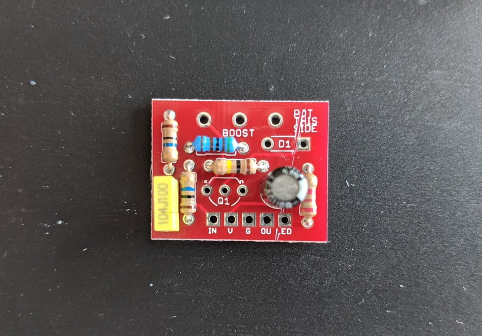
We’ll next move onto the clipping diode which in this circuit is a 9.1v Zener. Just like the electrolytic capacitor, this component is polarised and must be orientated correctly on the circuit. For this part, we need to ensure the side of the diode with the black band is aligned with the positive (Anode) square solder pad.

The next piece to add in is the BC170 transistor. I always recommend using a transistor socket to connect transistors to my boards as it will ensure you don’t overheat the transistor and it will also mean you can swap out different transistors to check which works best for you. These are very cheap and will save you a lot of desoldering hassle if you ever needed to swap them out. All BC170 transistors should use the same pin layout so it’s a case of matching the shape of the transistor up to the shape on the board but if you’re not sure, refer to the transistors datasheets.
The final component to add to the PCB is the 5K logarithmic potentiometer. You can solder this directly onto the board or use connection wires. I would recommend going straight onto the board as it makes the footprint much smaller and neater.
With all of these bits in place, the PCB is fully populated and ready to test.
Test Circuit
Before adding the completed PCB to the enclosure, we should be testing it to make sure it works correctly. It’s much easier to swap out parts outside of an enclosure than it is once everything has been put together.
To test the circuit, wire it up directly to your DC jack and ¼ inch input jacks. The wiring here doesn’t need to be that neat as we’ll be redoing all of these connections once we’re happy the circuit actually works.
You may notice a bit of interference with the sound at this stage but that is to be expected as there’s no shielding around the pedal. Once everything is in the metal Hammond enclosure, the circuit will be shielded removing all of this noise. If you choose to use an enclosure that isn’t metal, you’ll need to think about shielding.
When you’re happy that the pedal works and sounds like it should, we can prepare the enclosure.
Drill Enclosure
As previously mentioned, this pedal only requires one knob so we don’t need to drill too many holes.
Below is a guide for how big each of these holes needs to be:
1 Potentiometer – 8mm
1 LED Bezel – 8mm
2 Input Jacks – 10mm
1 DC input Jack – 12mm
1 3PDT Footswitch – 12mm
You can find my drilling guide for this pedal here:
Final Assembly
With all of the necessary holes drilled into your enclosure, we can start fitting the hardware.
Take all of the nuts and washers from the potentiometer, jacks and footswitch.
Put each piece through the correct hole and add the washers & nuts. Don’t fully tighten everything just yet as things may need to rotate slightly to fit the board and wires.
With all the hardware in place, we need to reassemble the pedal and connect the PCB to all of the components. As the hardware was in place first, we should be able to make the cables much shorter and cleaner making any future troubleshooting much easier.
Test Pedal
With everything fully wired up, it’s time to add it to your pedalboard with everything else and plug it in! You should notice that any interference you found during the testing phase has been fixed, but if any new noises appear, you can narrow it down to a poor connection with your hardware.
If you notice any new strange noises, check out my DIY guitar effects pedal troubleshooting guide.
Finishing Thoughts
When you first plug this pedal in, you definitely need to make sure that the potentiometer is turned right down. As it’s such a gigantic signal boost, it can really catch you out if you’re turned up straight out of the gate.
You may notice a little bit of a crackling noise when turning the gain knob but this is nothing to be concerned about, it’s just the BS170 transistor rebiasing.
